SIEMENS - CAPACITOR
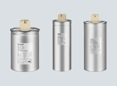
SIEMENS CAPACITOR range of capacitor can withstand high
inrush currents caused while individual switching operation
(>100IR) as well while connected in parallel, i.e. as banks
when the inrush current is increased to ≥150 · IR. The high
inrush is because of the charging current comes from the
power line as well as from other capacitors connected in
parallel in the bank.
Siemens capacitor is based MPP technology
[Metalized of Zinc Al alloy over Polypropelyne dielectric] of film making with an impregnation of semi-dry biodegradable soft resin.
Special film-cutting technique (optimized combination
of wavy and smooth cuts) & heavy edge and produces
a maximum effective surface for the metal spraying or contacting process,
Siemens capacitors are most compact and light in weight


In case of electrical overload the dielectric in the breakdown channel is broken down into highly compressed plasma that explodes out of the breakdown channel and pushes the dielectric layers apart. The discharge continues within the spreading plasma via the metal layers so that the metal surrounding the faulty area is completely burnt out. This produces perfect isolation of the faulty area within microseconds. The self-healing process results in negligible capacitance loss less than 100 pF per event. The capacitor remains fully functional during the entire process.
At the end of the capacitor’s service life or when a high pressure forms inside the can, the overpressure disconnector is activated. The specially designed cover with an expansion bead moves upwards. Expansion beyond a certain degree will separate the wires and disconnect the capacitor safely from the line. The disconnector is separated at its breakpoint (small notch) and the flow of current to the capacitor windings is interrupted.

Capacitor, Power Factor Controller, Cap-Contactors and Detuned Reactor
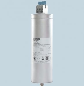
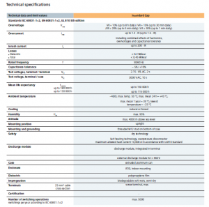
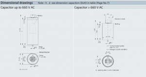
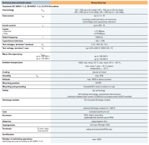
Standard Cap
Power Capacitors 3-phase, IP20
Overview
Standard Capacitors is based on the well-proven MKP technology with stacked windings, Standard capacitors are especially developed for Power Factor Correction applications in industrial installations.
The cost-effective design offers abroad output range from 0.5 to 33.0 kvar. The voltage range covers 230 to 525 VAC.
Benefit
- Compact design in cylindrical aluminum can with stud
- MKD technology with stacked windings
- Output range 0.5 – 33 kvar
- Voltage range 230 – 525 VAC
Applications
- Power Factor Correction
- Automatic capacitor banks
- Fixed PFC applications, e.g. motor compensation
- AC power electronics
- Tuned and detuned Power Factor Correction systems
Electrical
- Up to 33 kvar per capacitor for three-phase applications
- Long life expectancy up to 150,000 hours (at temperature class -40/C
- High inrush current withstand ability (up to 200 IR
Mechanical and maintenance
- Reduced mounting cost, easy installation and connection
- Low weight and compact volume
- Maintenance-free
Safety
- Self-healing technology
- Overpressure disconnector
- Isolated terminal (IP20)
PDF Download :
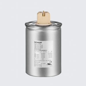
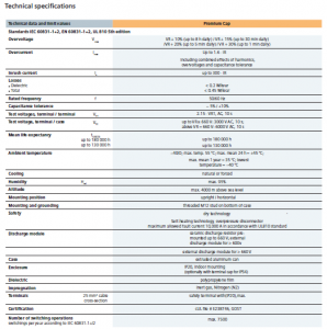
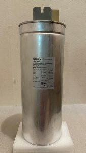
Premium Capacitor
Power Capacitors 3-phase, IP20
Overview
PremiumCap capacitors in cylindrical aluminum cases have been designed for power factor correction in low-voltage applications.
Loads like motors and transformers consume active power as well as reactive power.
Generators, supply cables and other electrical distribution equipment, in turn, should be relieved of reactive power.
The MKK (metalized plastic compact) AC series is intended to increase packing density per bank and cut component costs.
Improved thermal response and simplified installation are advantages of the cylindrical aluminum case.
Benefit
- Compact design in cylindrical aluminum can with stud Concentric winding
- MKK-technology with wavy cut and heavy edge
- Voltage range 230 V … 800 V
- Output range 5.0 kvar … 36 kvar
Applications
- Automatic PFC equipment, capacitor banks
- Individual fixed PFC (e.g. motors, transformers, lighting)
- Group fixed PFC
- Tuned and detuned capacitor banks
- Filter applications/ Dynamic PFC
Electrical
- Longlife expectancy
- High pulse current withstand capability
Mechanical and maintenance
- Reduced mounting cost, easy installation and connection
- Low weight and compact volume
- Maintenance-free
- Highest packing density thanks to compact dimensions
Safety
- Self-healing
- Overpressure disconnector
Shock hazard protected terminals - Longterm approved
cUL approval for B25667; for B25668 up to 690 V - Ceramic discharge resistor pre-mounted
Environmental
- Dry design, inert gas
- No oil leakagePremiun
PDF Download :
Benefits
• Display
– Large and multifunctional LCD (2 x 16 characters)
– Graphic and alphanumeric
– LCD illumination
• Intelligent control
• Menu-driven handling (plain language)
• Self-optimizing control capability
• Recall function of recorded values
• Four-quadrant operation (e.g. stand-by generator)
• Large measuring voltage range
• Powerful alarm output
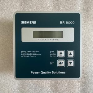
• Display of numerous of system parameters
– System voltage (V AC)
– Reactive power (kvar)
– Active power (kW)
– Frequency
– THD-V, THD-I
– Individual harmonics up to 19th
– Monitoring of individual capacitor currents
– Apparent power (kVA)
– Apparent current (A)
– Temperature (oC)
– Real-time cos
– Target cos
– kvar value to target cos
• Alarm output
– Insufficient compensation
– Overcomepensation
– Undercurrent
– Overcurrent
– Overtemperature
– Harmonics exceeded
– Threshold value programmable
– Internal error storage
– Programming of 2nd signal relay random
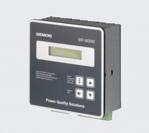
• Recall recorded values
– Number of contactor switching operations
– Maximum voltage V (Vmax)
– Maximum reactive power, Q (kvar)
– Maximum value of harmonic
– Maximum active power, P (kW)
– Maximum apparent power, S (kVA)
– Maximum temperature (oC)
– Operation time of all capacitors
• Complete 2nd parameter set available
• Automatic intialization
PDF Download :
- PFC BR6000 Technical Specification
- PRC BR6000 Manual
Controller BR7000 for Power Quality Solutions
The new power factor controller BR7000 is a follow-up development of the well-proven BR6000 series and offers a broad range of new characteristics and benefits. It can be used as a PF controller as well as a grid measuring device.
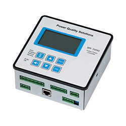
The BR7000 features 15 relay outputs for the steps and three message/ alarm relays.
These 15 outputs are programmable for different applications, for example:
■ 15 conventional steps, each for one three-phase capacitor.
■ 15 steps for single-phase capacitors. Each output will switch a single-phase capacitor to N, usually 5 per phase, balancing of the grid is possible.
Mixed operation, e.g. 6 singlephase capacitors (2 per phase) for balancing plus 9 steps for conventional compensation (three-phase capacitors).
The direct connection to a USS port of a PC via USS-adapter (Interface RS485) offers further benefits with the Windows software BR-Soft. The program allows a convenient visualization of grid parameters, analysis of recorded values and the graphical evaluation of all data received. Administration of several PF controllers is another advantage.
PDF Download :
- PFC BR7000 Technical Specification
- PRC BR7000 Manual
Overview
Standards
IEC/EN 60947-1, IEC/EN 60947-4-1, IEC/EN 60947-5-1,
IEC/EN 60831-1, IEC/EN 61921
Function
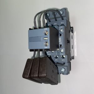
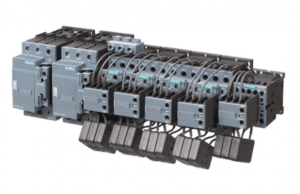
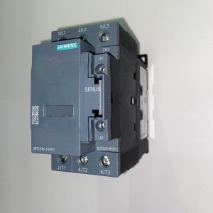
The 3RT26 contactors are special versions of the 3RT2, designed for switching capacitive loads (AC-6b) up to 100 kvar at 400 V.
Characteristic components of the 3RT26 contactors are the precharging resistors switched on via leading auxiliary contacts, which are closed before the main contacts. This limits the peak charging current of capacitive loads and thus minimizes negative impacts on the power supply network.
The 3RT26 contactors are suitable for switching choked or unchoked capacitors in reactive current compensation systems and are also used to switch converters.
Benefits
• Excellent damping of inrush current
• Improved power quality (e.g. avoidance of voltage sags)
• Longer useful service life of main contacts of capacitor contactor
• Soft switching of capcitor and thus longer useful service life
• Enhanced mean life expectancy of PFC system
• Reduced ohmic losses
• Leading contacts with wiper function
• Tamper-proof and protected resistors
• Easy access for cable connection
• Voltage range: 400 – 690 V
• Output range: 12.5 – 100 kvar
Auxiliary contacts
All 3RT26 contactors for capacitive loads are equipped with auxiliary contacts at the factory.
The 3RT261 and 3RT262 contactors are equipped with
a front-mounted auxiliary switch with integrated leading auxiliary contacts for the precharging resistors. A further fourth auxiliary contact in the auxiliary switch is unassigned.
A further freely assignable auxiliary contact is integrated in the basic unit of 3RT261; two of these are integrated in 3RT262.
In the case of the 3RT263 and 3RT264 contactors, the precharging resistors and their leading auxiliary contacts are integrated in the basic unit. These devices are supplied with an auxiliary switch mounted on the left, the auxiliary contacts of which are freely assignable.
Expansion is possible by means of an auxiliary switch with two auxiliary contacts on the right-hand side of the device.
Conductor cross-sections
In order to connect the required minimum cross-section, the use of an infeed terminal may be necessary, see page 3/117. This enables the connection of larger cross-sections than the device connection itself actually allows. For 3RT2628 contactors, this infeed terminal is already included in the scope of supply and is already mounted on the contactor.
Contact endurance of the main contacts
The characteristic curves show the contact endurance of the contactors when switching capacitive loads (AC-6b) depending on the reactive
power QN and rated operational voltage.
The rated operational current Ie in accordance with utilization category AC-6b (breaking of 1.35 times the rated operational current) is specified for a contact
endurance of approximately 150 000 to 200 000 operating cycles.
PDF Download :
Detuned reactor
Overview
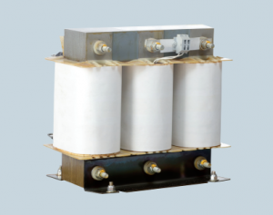
In past few years the use of power electronics equipment’s
like drives, SMPS, UPS etc has increased tremendously.
These devices distort the pure sinusoidal waveform of power
supply. These distortions can be called as harmonics. When
a capacitor is used for power factor correction, it might
create a resonating circuit with the feeding transformer. The
resonance frequency is generally from 250Hz to 500Hz, that
means 5th to 7th harmonics. This resonance is undesired
condition and it might lead to
• Overloading of capacitors- reduce the life of capacitor
• Overloading of transformer, cables and other switchgear
elements in the circuit- reduces life of all components
• Voltage distortion
• Increased power losses
• Nuisance tripping of protection equipment
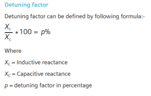
This resonance can be avoided by putting a detuned reactor
in series with the capacitor. The reactor shall be such that
the tuning frequency with capacitor shall be less than the
dominant harmonics. This combination of power factor
correction capacitor and detuned reactors behaves inductively
to frequencies above tuning frequency. Thus provide high
impedance path to harmonics present in the system.
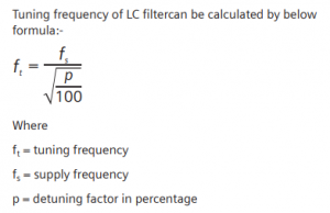
Tuning frequency of LC filter can be calculated by below
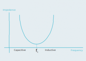
This combination of detuned LC filter will act capacitive for
frequency below ft and inductive for frequency above ft. Thus
for base frequency of 50 or 60Hz this detune filter will act as
capacitive and improves the power factor. This LC detuned
filter is selected such that the tuning frequency is much less
than the dominant harmonic frequency. Thus harmonics
always seeshigher impedance and the condition of resonance
with feeding transformeris avoided.
For example if the dominant harmonics is 5th harmonic
and base frequency is 50Hz, a 7% detuned reactor shall be
selected. The tuning frequency of this filter will be
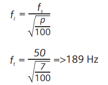
189Hz, the tuning frequency in this case is lesser then 250Hz,
the harmonic frequency. Hence there will not be a situation
of resonance between the feeding transformer and capacitor.
PDF Download :


25/236 Soi Samaedum 17, Samaedum, Bangkhuntain Bangkok 10150 ( Thailand) Tel.: 099-262-6556, 062-782-6559 Fax.: 02 896-1661
